Introduction
Software Defined Wide Area Network (SD-WAN) is a technology which increases performance and/or control of application traffic over redundant WAN interfaces and VPN links. The Allied Telesis SD-WAN solution is able to make routing decisions based on the quality of VPN links. To do this, it uses link probing to determine path quality and perform application-aware routing to dynamically redirect performance sensitive application traffic (for example voice or video) via redundant links that meet application performance requirements.
How does SD-WAN differ from 'conventional' Policy Based Route (PBR)?
When you create a conventional PBR rule, you must supply a list of nexthops. The traffic that matches the rule will be routed to the first nexthop in the list that is link up. If you configure a list of three links, and link 1 goes down, link 2 will automatically be used instead. When link 1 comes back up it will again be re-used.
SD-WAN extends this concept beyond simply checking if a link is up or down. It can also use metrics about the health of the link to decide if the link is “good” or “bad”. This allows traffic to be re-directed from a “bad” link to a “good” link, even if both links are still up. The metrics that SD-WAN can use to judge the health of a link are jitter, latency, packet-loss, and consecutive probe loss. Each metric is examined separately, so that a link that is “bad” for voice traffic due to high latency may still be “good” for bulk data due to low packet loss.
Components of SD-WAN Load Balancing
SD-WAN load balancing has four major components:
It is used to redirect traffic which matches the defined match criteria from the standard routing path to a defined nexthop.
ip policy-route [<1-500>] [match <application_name>] [from <source_entity>]
 [to <destination_entity>] linkmon-group <name> [linkmon-profile <name>]
A linkmon group is a collection of nexthops that can be used by the associated policy-route. Each linkmon group can have up to eight nexthops, known as members.
linkmon group <name> member [<member-id>] destination <ip-address>|<interface>
 probe <probe-name>
A linkmon probe is used to determine latency, jitter, packet-loss, and consecutive probe loss for a given member.
linkmon probe name <NAME> [type <icmp-ping|http-get>]
Linkmon probe options:
destination <A.B.C.D|X:X::X:X|ds-lite|FQDN>
dscp <0-63>
egress interface <interface>
interval <probe-interval>
ip-version <4|6>
sample-size <1-100>
size <64-1500>
source <interface|IPv4-address>
Note: Linkmon probes are disabled by default, and must be enabled per-probe using the enable command.
A linkmon profile is used to define what are acceptable metrics for a given linkmon ip policy-route.
linkmon profile <name>
Linkmon profile configuration commands:
latency bad-above <1-2000>
latency good-below <1-2000>
jitter bad-above <1-1000>
jitter good-below <1-1000>
pktloss bad-above <0.0-100.0>
pktloss good-below <0.0-100.0>
preference (latency|jitter|pktloss|consecutive-probe-loss|combined)
Optional commands
linkmon probe-history [<1-65535>] probe <NAME> interval <1-2678400> buckets <1-65535>
This command allows you to create a historic data capture for linkmon probes. A custom interval can be configured and a number of buckets, allowing metric data to be flexibly recorded for hours, days, weeks, or months, with resolutions as low as 1 second or as high as days.
Configuring linkmon probe history is not required for operating SD-WAN. However, it is useful in diagnosing unexpected routing failures.
Configuration Examples - Application Aware Routing Via Redundant VPNs
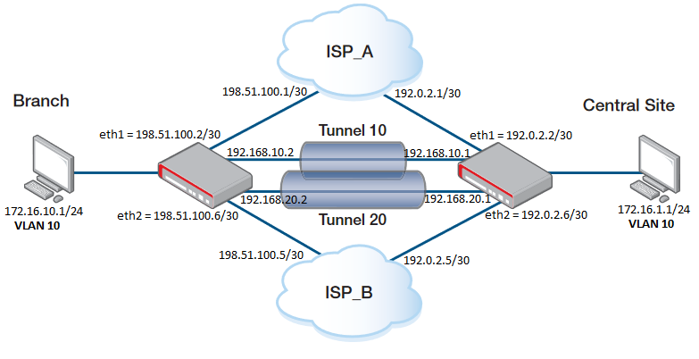
Configuration on the BRANCH side:
Step 1. Add the IP address to the interfaces.
interface eth1
 ip address 198.51.100.2/30

interface eth2
 ip address 198.51.100.6/30

interface vlan10
 ip address 172.16.10.1/24
Step 2. Create a tunnel interface.
interface tunnel10
 tunnel source eth1
 tunnel destination 192.0.2.2
 tunnel local name TUNNEL10
 tunnel remote name TUNNEL10
 tunnel protection ipsec
 tunnel mode ipsec ipv4
 ip address 192.168.10.2/30

interface tunnel20
 tunnel source eth2
 tunnel destination 192.0.2.6
 tunnel local name TUNNEL20
 tunnel remote name TUNNEL20
 tunnel protection ipsec
 tunnel mode ipsec ipv4
 ip address 192.168.20.2/30
Note that you need to designate a tunnel mode, tunnel source address, tunnel destination address, IP address of tunnel interface and use tunnel protection ipsec (IPsec) command to encrypt and authenticate the packets travelling though the tunnel.
The destination on Tunnel 10 will be the ETH1 on Central Site.
The destination on Tunnel 20 will be the ETH2 on Central Site.
Step 3. Define the Entities.
zone CENTRAL_WAN
 network ETH1
  ip subnet 192.0.2.2/32 interface eth1
 network ETH2
  ip subnet 192.0.2.6/32 interface eth2

zone LAN
 network TUNNEL
  ip subnet 192.168.10.0/30 interface tunnel10
  ip subnet 192.168.20.0/30 interface tunnel20
 network VLAN10
  ip subnet 172.16.10.0/24 interface vlan10
 network CENTRAL_LAN
  ip subnet 172.16.1.0/24

zone WAN
 network ETH
  ip subnet 0.0.0.0/0 interface eth1
  ip subnet 0.0.0.0/0 interface eth2
 host HOST
  ip address 198.51.100.2
  ip address 198.51.100.6
Step 4. Define applications for the VPN tunnel.
application esp
 protocol 50

application isakmp
 protocol udp
 dport 500
Step 5. Configure an ISAKMP authentication key.
crypto isakmp key <samplekey1> hostname TUNNEL10
crypto isakmp key <samplekey2> hostname TUNNEL20
Note: The <key> should be the same on both sides (Branch and Central Site).
Step 6. Define the PBR to describes which traffic to match and where to route it.
policy-based-routing
 ip policy-route 10 match sip from LAN.VLAN10 linkmon-group GROUP1 linkmon PROFILE1
 ip policy-route 20 match rtp from LAN.VLAN10 linkmon-group GROUP1 linkmon PROFILE1
 ip policy-route 30 match rtcp from LAN.VLAN10 linkmon-group GROUP1 linkmon PROFILE1
 policy-based-routing enable
Step 7. Define a linkmon probe used to determine the quality of a link.
linkmon probe name PROBE1
 destination 192.168.10.1
 enable

linkmon probe name PROBE2
 destination 192.168.20.1
 enable
Step 8. Define a list of possible nexthops as known linkmon members. Each member is associated with a probe.
linkmon group GROUP1
 member 10 destination tunnel20 probe PROBE2
 member 20 destination tunnel10 probe PROBE1
Step 9. Define the acceptable metrics for a given link.
linkmon profile PROFILE1
 latency bad-above 150
 latency good-below 100
 jitter bad-above 40
 jitter good-below 20
 consecutive-probe-loss good-when 3
 consecutive-probe-loss bad-when 4
 consecutive-probe-loss unreachable-when 7
Step 10. Allows DPI to re-inspect traffic after VPN decapsulation enabling stream security reprocessing on all tunnel interfaces.
tunnel security-reprocessing
Step 11. Adds the neccesary static routes to ensure comunication between the two ends.
ip route 0.0.0.0/0 198.51.100.1
ip route 0.0.0.0/0 198.51.100.5 254
ip route 172.16.1.0/24 tunnel10
ip route 192.0.2.0/30 198.51.100.1
ip route 192.0.2.0/30 Null 254
ip route 192.0.2.4/30 198.51.100.5
ip route 192.0.2.4/30 Null 254
Step 12. Define the Firewall and NAT rules.
firewall
 rule 10 permit any from LAN to LAN
 rule 20 permit any from LAN to WAN
 rule 30 permit isakmp from CENTRAL_WAN to WAN
 rule 40 permit esp from CENTRAL_WAN to WAN
 rule 50 permit any from WAN.ETH.HOST to WAN.ETH
 protect

nat
 rule 10 masq any from LAN.VLAN10 to WAN
 enable
The configuration on the CENTRAL_SITE would be the same, changing the corresponding Entity names and IP addresses and the PBR which is changed from "From" to "To" because the traffic is matched coming from the CENTRAL_SITE.
policy-based-routing
 ip policy-route 10 match sip to LAN.BRANCH_LAN linkmon-group GROUP1 linkmon PROFILE1
 ip policy-route 20 match rtp to LAN.BRANCH_LAN linkmon-group GROUP1 linkmon PROFILE1
 ip policy-route 30 match rtcp to LAN.BRANCH_LAN linkmon-group GROUP1 linkmon PROFILE1
 policy-based-routing enable
Some Show commands
To show information about Link Health Monitoring probe metric history collection instances, use the following command:
awplus#show linkmon probe-history
You need to previously create a collection instance that records the metrics gathered by a Link Health Monitoring probe.
awplus#show linkmon probe-history
--------------------------------------------------------------------------------
ID     Interval (s)      Buckets   Latency (ms): Min           Max           Avg
Probe                               Jitter (ms): Min           Max           Avg
                                        Packets:  Tx            Rx      Loss (%)
--------------------------------------------------------------------------------
10                5      100/100                   0             1             0
PROBE1                                             0             0             0
                                                 500           500          0.00
11                5      100/100                   0             1             0
PROBE2                                             0             0             0
                                                 500           500          0.00
To show all configuration for PBR rules, use the following command:
awplus#show pbr rules
To show the configuration for a specific linkmon profile named “PROFILE1”, use the following command:
awplus#show pbr rules profile PROFILE1
To show the configuration for a specific linkmon group named “GROUP1”, use the following command:
awplus#show pbr rules group GROUP1
To show a summary of all PBR rules and which nexthop to route to, use the following command:
awplus#show pbr rules brief
Policy based routing is enabled
Route table usage: 2/62
* - No route table available for the rule - see "show ip pbr route"
Rule Match            From            To              Valid Nexthop
----------------------------------------------------------------------------
 1   any              LAN.VLAN10      any             Yes   -
 10  any              LAN.VLAN10      any             Yes   -
For more information about SD-WAN and how to use IPv6, please refer to the Configuration Guide:
SD-WAN feature overview and configuration guide