Introduction
Power over Ethernet (PoE) simplifies deployment—delivering power and data over the same cable for easy installation.
the Allied Telesis range of PoE ethernet switches connect and power IP phones, wireless APs, video surveillance cameras and more,
enabling easy to manage solutions for any application and budget.
This article will help you trouble shoot PoE issue with Allied Telesis switches.
First ensure that the switch supports PoE
- Check the switch's datasheet.
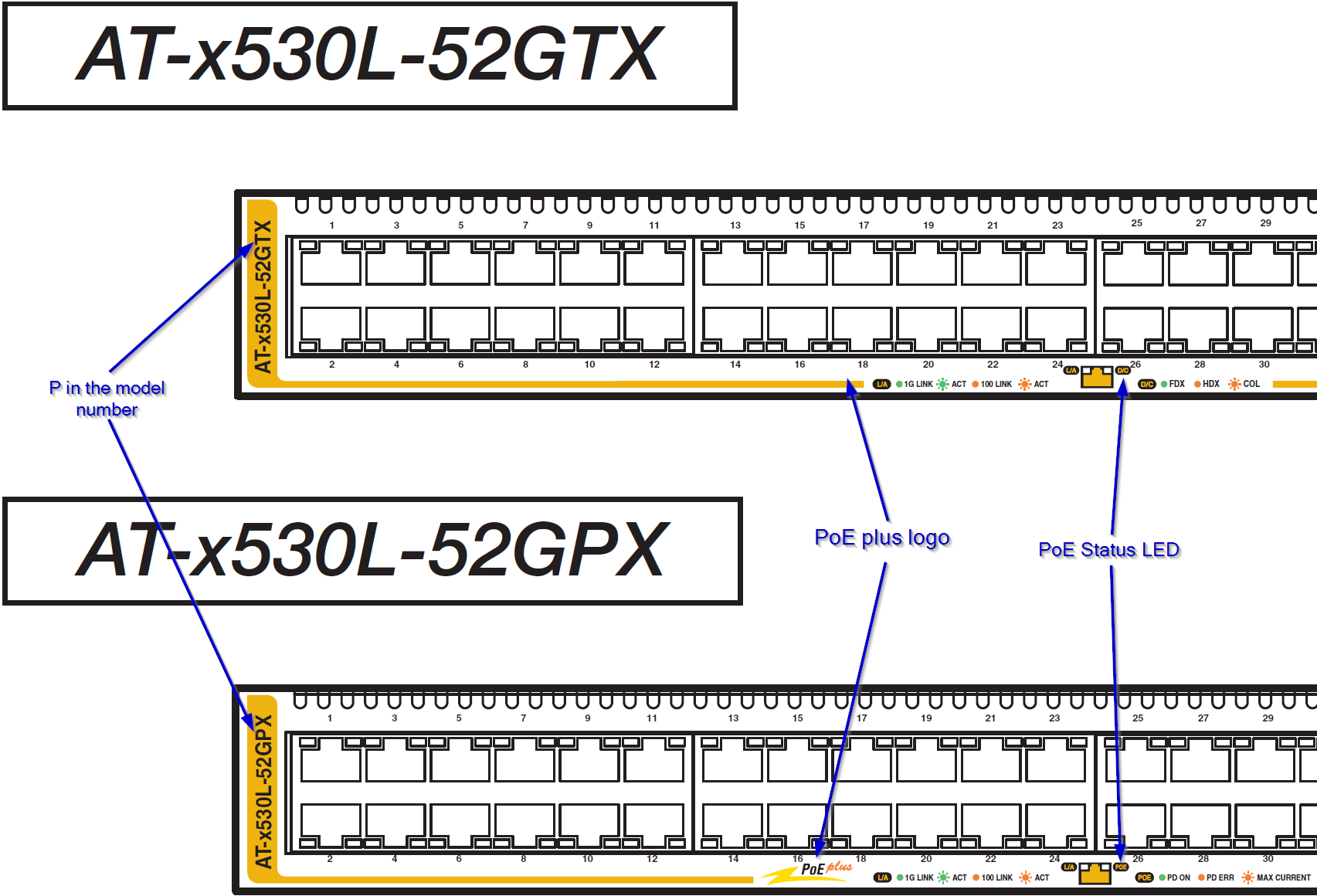
- Look for PS/GP/POE/MPX in model number(below example shows AT-x530L-52GTX vs AT-x530L-52GPX).
- Look for PoE plus logo on the right side of the switch.
- Look for LED legend on the front panel, POE switch will have LED indicator for PoE while non-PoE switch have duplex indicator instead.
Second, ensure that the power supply is functioning correctly
If the power supply is not receiving enough power or is malfunctioning, it may affect PoE output of the switch.
Run show system environment command on the switch to display the details.
If the status shows fault, please contact Allied Telesis Support.
awplus# show system environment ↓
Environment Monitoring Status

Overall Status: Normal

Resource ID: 1  Name: PSU 1 ()
ID  Sensor (Units)                      Reading  Low Limit High Limit Status
1   Device Present                          Yes        -          -       Ok
2   PSU Power Output                     Yes        -          -       Ok

Resource ID: 2  Name: PSU 2 ()
ID  Sensor (Units)                      Reading  Low Limit High Limit Status
1   Device Present                          Yes        -          -       Ok
2   PSU Power Output                     Yes        -          -       Ok

Resource ID: 3  Name: AT-x530-28GTXm
ID  Sensor (Units)                      Reading  Low Limit High Limit Status
1   Fan: Fan 1 (Rpm)                         3633       2025        -       Ok
2   Voltage: 1.2V (Volts)                 1.261      1.079      1.313     Ok
3   Voltage: 0.98V (Volts)               0.996      0.879      1.066     Ok
4   Voltage: 3.3V (Volts)                 3.347      2.960      3.613     Ok
5   Voltage: 1.5V (Volts)                 1.518      1.335      1.649     Ok
6   Voltage: 1.5V (Volts)                 1.507      1.292      1.600     Ok
7   Temp: Remote1 (Degrees C)             33        -11         63     Ok
8   Temp: System (Degrees C)                35        -11         67     Ok
9   Temp: Remote2 (Degrees C)             36        -11         68     Ok
10  Voltage: 2.5V (Volts)                 2.531      2.339      2.859     Ok
11  Voltage: 1.8V (Volts)                 1.816      1.617      1.969     Ok
12  Voltage: 0.8V (Volts)                 0.812      0.707      0.864     Ok
13  Voltage: 0.9V (Volts)                 0.907      0.800      0.984     Ok
14  Temp: Remote1 (Degrees C)             29        -11         57     Ok
15  Temp: System (Degrees C)                36        -11         68     Ok
16  Temp: Remote2 (Degrees C)             44        -11         72     Ok
Third, ensure that the power allocation is not exceeding the power budget
Some Powered Devices do not report their PoE power classification. This is an optional step that the Powered Camera or Phone manufacturer must take while making these items.
In the instances where this has not been done, the switch will read the port as a Class 0 PoE device and will, by default, reserve the maximum available power for that port.
This will cause the switch quickly run exceed the PoE budget and stop allocating PoE power as new devices are connected.
For example, the switch will supply PoE power to first 8 ports but nothing else.
Run command show power-inline to find out the status of the power over ethernet:
This command will show output as below:
awplus# show power-inline ↓
PoE Status:

Stack Member 1
 Nominal Power: 370W
 Power Allocated: 358W
 Actual Power Consumption: 50W
 Operational Status: On
 Power Usage Threshold: 80% (296W)
 Detection of legacy devices is enabled
 Power Source: PSU
 Power management mode: Dynamic

PoE Interface:
Interface   Admin     Pri   Oper      Power  Device            Class  Max
                                       (mW)                           (mW)
port1.0.1   Enabled   Low   Powered    1877  n/a                   1   4053 [C]
port1.0.2   Enabled   Low   Powered    5464  n/a                   2   7295 [C]
port1.0.3   Enabled   Low   Powered    3759  n/a                   3  15400 [C]
...
If the Allocated power is exceeding the rated power of the PoE equipment, limit the allocated power to each port based upon its need as show below. This will reduce the total allocated power.
awplus(config)# interface port1.0.1 ↓
awplus(config-if)# power-inline max 6000 ↓
the above command limits port1.0.1's allocated power to 6000mW(6W).