Introduction
PIM Sparse Mode (PIM-SM) is designed on the principle that several hosts wishing to receive a multicast stream does not justify flooding the entire network with periodic multicast traffic. PIM-SM is designed to limit multicast traffic so that only those switches interested in receiving traffic for a particular group receive the traffic.
Switches with directly attached or downstream members of a given group are required to join a Sparse Mode distribution tree by transmitting explicit join messages. If a switch does not become part of the distribution tree for a group, it does not receive multicast traffic addressed to the group. In contrast, Dense Mode multicast routing protocols assume downstream group membership and continue to forward multicast traffic on downstream links until explicit prune messages are received. The default forwarding action of a Sparse Mode multicast routing protocol is to block traffic unless it is explicitly requested, while the default action of the Dense Mode multicast routing protocols is to forward traffic, unless requested not to.
In PIM Sparse Mode, a router will not know the source IP of a stream that is it not currently forwarding. As a result, Sparse Mode routers need a way to find out the source IPs of the streams for which they receive downstream requests. To solve this, Sparse Mode introduces the concept of Rendezvous Points (RPs) – specific designated routers that receive notification of all streams destined to specific ranges of multicast addresses (or, possibly, all multicast addresses). In turn, the introduction of Rendezvous Points into the protocol requires that the protocol also provide a way that routers find out the identities of the Rendezvous Points.
Hence Sparse Mode has the concept of a Bootstrap Router (BSR) that knows the identities of the RPs and provides this information to all other routers. In addition, the protocol needs a process by which the RPs are notified of new streams, and a process whereby a router, having learnt the source IP of a stream from the RP, then accesses the stream via a direct path from the source.
Roles in PIM-SM
A multicast sender does not need to know the addresses of the members of the group in order to send to them, and the members of the group need not know the address of the sender. Group membership can change at any time. When PIM is enabled on the switch, and before the switch can route multicast traffic, it must establish which of the PIM routers in the network are performing some key roles:
- Designated Router (DR) - There must be one PIM Designated Router in each subnet in the network. Any PIM-SM interfaces on the subnet elect the DR with the highest DR priority.
- Rendezvous Point (RP) - Each multicast group must have a Rendezvous Point.The DR on the subnet containing a multicast source sends multicast packets towards the RP. DRs with group members connected to them send join messages towards the group’s RP.
- Bootstrap Router (BSR) - Again, the Bootstrap Router for a network is chosen by election. A number of routers in the network can be configured to be candidates for the BSR role. Each PIM-SM network must have at least one Bootstrap Router candidate, unless all switches in the domain are configured statically with information about all RPs in the domain.
PIM-SM Configuration
PIM-SM can be configured using three types of deployment models. Static, dynamic, or Bootstrap Router configuration options are available to meet your particular multicast needs. For this document, we are looking at The Dynamic Rendezvous Point model deployment.
A static RP configuration works for a small, stable PIM domain. However, it is not practical for a large and not so stable network. In such a network, if the RP fails, the network administrator may have to change the static configurations on all PIM switches. A major reason for choosing dynamic configuration is because changes in routing traffic levels might require a change in the RP.
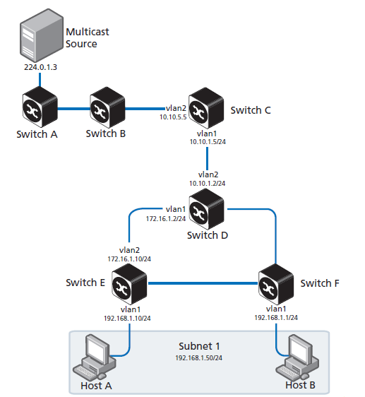
This Rendezvous Point configuration example refer to the network topology in the following graphic and the use of Allied Telesis managed Layer 3 Switches as the PIM routers.
Below is the multicast configuration for Switch C:
Switch_C#show run
!
interface vlan1
ip pim sparse-mode
!
interface vlan2
ip pim sparse-mode
!
ip multicast-routing
ip pim rp-candidate vlan1
Here is the multicast configuration for Switch D:
Switch_D#show run
!
interface vlan1
ip pim sparse-mode
!
interface vlan2
ip pim sparse-mode
!
ip multicast-routing
ip pim bsr-candidate vlan1
ip pim rp-candidate vlan1 priority 2
The highest priority switch is chosen as the RP. If two or more switches have the same priority, a hash function in the BSR mechanism is used to choose the RP to make sure that all devices in the PIM domain have the same RP for the same multicast group.
Use the <interface> [priority <priority>] parameters of the ip pim rp-candidate command to change the default priority of any RP candidate.
Helpful PIM-SM Commands for above example
The show ip pim sparse-mode rp mapping command displays the group-to-RP mapping details.
The output shows information about RP candidates. There are two RP candidates for the group range 224.0.0.0/4. RP candidate 10.10.1.5 has a default priority of 192, whereas RP candidate 172.16.1.2 has been configured to have a priority of 2. Since RP candidate 172.16.1.2 has a higher priority, it is selected as the RP for the multicast group 224.0.0.0/4.
Switch_D#show ip pim sparse-mode rp mapping
This system is the Bootstrap Router (v2)
Group(s): 224.0.0.0/4
RP: 10.10.1.5
Info source: 172.16.1.2, via bootstrap, priority 192
Uptime: 00:00:13, expires: 00:02:29
RP: 172.16.1.2
Info source: 172.16.1.2, via bootstrap, priority 2
Uptime: 00:34:42, expires: 00:01:49
The show ip pim sparse-mode rp-hash command displays information about the RP router for a particular group. See the following configuration output for Switch D.
Switch_D#show ip pim sparse-mode rp-hash 224.0.1.3
Group(s): 224.0.0.0/4
RP: 172.16.1.2
Info source: 172.16.1.2, via bootstrap
This output shows that 172.16.1.2 has been chosen as the RP for the multicast group 224.0.1.3. After RP information reaches all PIM switches in the domain, various state machines maintain all routing states as the result of Join/Prune messages from members of the multicast group.
Additional details for all three deployment models can be found in the Protocol Independent Multicast - Sparse Mode (PIM-SM) Feature overview and Configuration Guide found on our web site.