Introduction
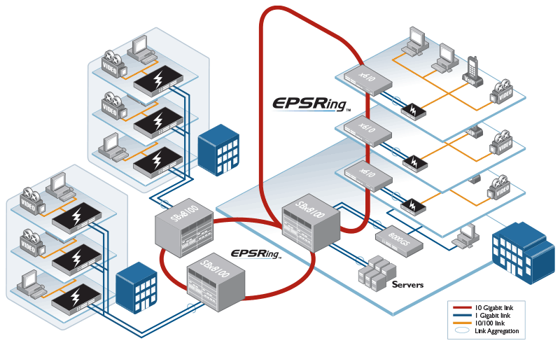
Allied Telesis Ethernet Protection Switched Ring (EPSRing) solutions provide high performance, high reliability, flexible, scalable distributed network cores. The core can be as small or as large as you need. It can be connected by copper or fiber, or even copper and fiber in the same ring. The core bandwidth can be anything from 100Mbps to multiples of 10Gbps.
EPSR enables rings to recover rapidly from link or node failures, within as little as 50 ms, depending on port type and configuration, making this solution ideal for the provision of converged voice, video and data services.
EPSR does not in itself limit the number of nodes that can exist on any given ring. For information on ring limits, refer to the EPSR feature overview guide on page 5.
You can mix different switch series in one ring, but its not recommended to mix different bandwidths, i.e. you can have a link between two switches at 10G and in other part of the ring a link at 1G, this could result in lost of packets and misbehavior of some protocols.
How to Configure EPSR
On each switch, perform the following configuration steps. Configuration of the master node and each transit node is very similar.
1.Configure the control and data VLAN.
This step creates the control and data VLANs for EPSR.
awplus(config)#vlan database
awplus(config-vlan)#vlan <control-vid> name <control-vlan-name>
awplus(config-vlan)#vlan <data-vid> name <data-vlan-name>
2. Configure the switch ports.
This step sets the rings ports to VLAN trunk mode and adds the control and data VLANs.
awplus(config)#interface <port-number>
awplus(config-if)#switchport mode trunk
awplus(config-if)#switchport trunk allowed vlan add <control-vid,data-vid>
awplus(config-if)#switchport trunk native vlan none
The final command removes the native VLAN (vlan1) from the ring ports. If you leave all the ring ports in the native VLAN, they will create a loop, unless vlan1 is part of the EPSR domain.
3. Configure the EPSR domain.
This step creates the domain, specifying whether the switch is the master node or a transit node. It also specifies which VLAN is the control VLAN, and on the master node which port is the primary port.
On the master node:
awplus(config)#epsr configuration
awplus(config-epsr)#epsr <name> mode master controlvlan <control-vid> primaryport <port-number>
awplus(config-epsr)#epsr <name> datavlan <data-vid>
On each transit node:
awplus(config)#epsr configuration
awplus(config-epsr)#epsr <name> mode transit controlvlan <control-vid>
awplus(config-epsr)#epsr <name> datavlan <data-vid>
4. Enable EPSR.
This step enables the domain on each switch.
awplus(config-epsr)#epsr <name> state enabled
Note: It is possible to configure RSTP and EPSR protocols on a single device. However, it is not possible to run both EPSR and RSTP on the same ports. RSTP is automatically disabled on a port when it is added to an EPSR VLAN.
EPSR show commands
To display the EPSR state, the attached VLANs, the ring ports, and the timer values, use the command:
awplus# show epsr
Show EPSR on Master node
In a complete ring, the state is shown as Complete. It also shows the primary and the secondary port. The secondary port will be shown as Blocked, so does not forward packets over the data VLAN.
In case that the ring is broken, the status will be shown as Failed and both ring ports will be forwarding.
Show EPSR on Transit node
In a fully forwarding state, the State will be shown as Links-Up and both of its ring ports are forwarding.
The EPSR counters record the number of EPSR messages that the CPU received and transmitted. To display the counters, use the command:
awplus# show epsr <epsr-name> count
You will see the difference between the Received and Transmitted packets.
On the Master node, if they are not close, the ring is broken.
On a Transit node you will see a lot of Receive EPSR Packets and if you keep repeating the command, the "Total EPSR Packets" and the "Health" packets increment should be the same.
Note: The Transmit counters will not be increased on the Transit node because they are transmitted by the switching hardware, not the CPU.
To check the configuration of all EPSR instances and display the results, use the command:
awplus# show epsr config-check